
Tolerance Stacking Methods and Effective Practices
Explore precision engineering with our guide on tolerance stacking. Discover essential analysis methods and industry practices to elevate your design precision.
Precision in mechanical design is a crucial thing in which effective tolerance stacking is highly important. It is essential to incorporate a fine balance of tolerance in a mechanical assembly. To ensure such, manufacturers use various Tolerance stacking methods and effective practices.
The most prominent methods of tolerance stack-up are Statistical Tolerance Analysis, GD&T, the use of results from tolerance tests & feedback, root sum squares, worst-case analysis, and so on.
In this article, we explore every aspect of these methods while elaborating on effective practices to hit the fine-balance parameter of tolerance. Let’s start.
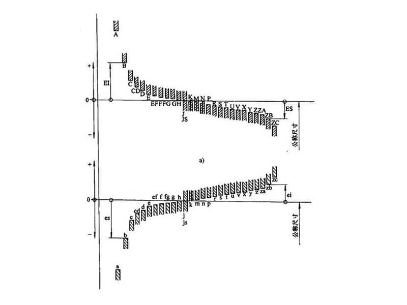
Basics of Tolerance Stacking
When multiple parts are assembled together to develop a certain mechanical part, the total impact of individual components becomes crucial. This impact of individual parts’ tolerances triggers several variations, which can negatively affect the performance of the assembled part.
Here, tolerance stacking becomes handy as it triggers the opportunity to control and manage the oriented variations effectively. Tolerance stack-up allows engineers, manufacturers, and product designers to produce a final part’s components with specified tolerances.
We would like to notify that this action not only ensures the proper function of the whole assembly but also ensures proper fits of the components within the assembly.
Methods of Tolerance Stacking
In the introduction section, we have already mentioned various methods of tolerance stacking. By considering the output’s higher level of precision, we apply statistical tolerance analysis, GD&T, and worst-case analysis.
The following are the detailed discussions of each method.
Statistical Tolerance Analysis
This method is highly effective in matching precision and practicality. It considers the probabilistic tendency of developing a part by assembling small components.
The statistical tolerance analysis method does not go for any fixed tolerance value of the single components. It counts on a crystal clear understanding of the variations affecting tolerance.
Finally, it allows the manufacturers to manage those variations effectively. So that the assembled part does not break down while testing or functioning. This tolerance stacking method uses some popular statistic analysis tools like Six Sigma Principles and the RSS method.
Six Sigma Principles
In the case of tolerance stacking, the Six Sigma method is crucial to reduce variations as much as possible. Here, the target is to restrict the defect rate to 3.4 per million opportunities. To get such, first, manufacturers find the value of DPMO, i.e., Defects Per Million Opportunities.
They use the below formula:
DPMO=Number of Opportunities/ Number of Defects x 1,000,000
The DPMO value is then used to determine each process’s sigma value. The formula is below:
σ =1/DPMO ^ 1/3.41
If the sigma value is not satisfactory, the professionals use the DMAIC methodology to come up with a suitable shaping of the component. It is a repetitive process and continues till the sigma reaches 3.41 or near value.
RSS Method
The full form of RSS is the Root Sum Squared. Here, each component’s tolerance value is squared at first. Then, all the values of squared tolerances are summed up.
Finally, the calculation includes finding the root value of the sum to find the value of tolerance stacking of the whole assembly.
Below is the formula:
T total= √(T12+T22+…+Tn2)
Here, T is the tolerance of the respective component, and n is the number of components.
GD&T Method
Geometric Dimensioning and Tolerancing is a specialized language. This symbolic language is used to incorporate design specifications and tolerances more accurately. The following are the stepwise guidelines for using this method in tolerance stacking.
Worst-case Analysis
This method of tolerance stack-up considers systematic evaluation of the resulting impact of individual components’ tolerance on the whole assembly. It acts as a guide to incorporate the required modification of shape, size, and position of individual components in a final part.
The following is the stepwise guideline.
Effective Practices for Tolerance Stacking
The following are the best practices for tolerance stacking.
Final Words
We hope our in-depth discussion on tolerance stacking methods and effective practices greatly benefits every stakeholder, from designers to users.
Finally, applying as many methods as possible to make an assembly precise and highly functional is necessary. If you are looking for a manufacturer that can provide such, contact us now!
Related Blogs


Looking for a trustworthy Supplier
Need a Trustworthy Supplier of Plastic, Foam, Sponge, Rubber, Metal, and Machining Solution. Click the Button, We Will Be In Touch With You As Quickly As Possible.